
Wednesday, February 11, 2015
Thursday, February 5, 2015
Beating Heart animation on 8x8 LED Matrix + Arduino Uno
This example run on Arduino uno, animate beating heart on 8x8 LED Matrix.

Example code:
Example code:
// 2-dimensional array of row pin numbers:
const int row[8] = {
  2, 7, 19, 5, 13, 18, 12, 16
};

// 2-dimensional array of column pin numbers:
const int col[8] = {
  6, 11, 10, 3, 17, 4, 8, 9
};

// 2-dimensional array of pixels:
int pixels[8][8];

int count = 1000;

char str[] = "FABCDEDCBA";
int strLen = sizeof(str);
int ptrChar = 0;


typedef bool charMapType[8][8];

const charMapType charBlank = {
  {0, 0, 0, 0, 0, 0, 0, 0},
  {0, 0, 0, 0, 0, 0, 0, 0},
  {0, 0, 0, 0, 0, 0, 0, 0},
  {0, 0, 0, 0, 0, 0, 0, 0},
  {0, 0, 0, 0, 0, 0, 0, 0},
  {0, 0, 0, 0, 0, 0, 0, 0},
  {0, 0, 0, 0, 0, 0, 0, 0},
  {0, 0, 0, 0, 0, 0, 0, 0}
};

const charMapType heart0 = {
  {0, 0, 0, 0, 0, 0, 0, 0},
  {0, 0, 0, 0, 0, 0, 0, 0},
  {0, 0, 0, 0, 0, 0, 0, 0},
  {0, 0, 0, 0, 0, 0, 0, 0},
  {0, 0, 0, 1, 1, 0, 0, 0},
  {0, 0, 0, 1, 1, 0, 0, 0},
  {0, 0, 0, 0, 0, 0, 0, 0},
  {0, 0, 0, 0, 0, 0, 0, 0}
};

const charMapType heart1 = {
  {0, 0, 0, 0, 0, 0, 0, 0},
  {0, 0, 0, 0, 0, 0, 0, 0},
  {0, 0, 0, 0, 0, 0, 0, 0},
  {0, 0, 0, 1, 1, 0, 0, 0},
  {0, 0, 1, 1, 1, 1, 0, 0},
  {0, 0, 1, 1, 1, 1, 0, 0},
  {0, 0, 0, 1, 1, 0, 0, 0},
  {0, 0, 0, 0, 0, 0, 0, 0}
};

const charMapType heart2 = {
  {0, 0, 0, 0, 0, 0, 0, 0},
  {0, 0, 0, 0, 0, 0, 0, 0},
  {0, 1, 1, 0, 0, 1, 1, 0},
  {1, 1, 1, 1, 1, 1, 1, 1},
  {1, 1, 1, 1, 1, 1, 1, 1},
  {0, 1, 1, 1, 1, 1, 1, 0},
  {0, 0, 1, 1, 1, 1, 0, 0},
  {0, 0, 0, 1, 1, 0, 0, 0}
};

const charMapType heart3 = {
  {0, 0, 0, 0, 0, 0, 0, 0},
  {0, 1, 1, 0, 0, 1, 1, 0},
  {1, 1, 1, 1, 1, 1, 1, 1},
  {1, 1, 1, 1, 1, 1, 1, 1},
  {0, 1, 1, 1, 1, 1, 1, 0},
  {0, 0, 1, 1, 1, 1, 0, 0},
  {0, 0, 0, 1, 1, 0, 0, 0},
  {0, 0, 0, 0, 0, 0, 0, 0}
};

const charMapType heart4 = {
  {0, 1, 1, 0, 0, 1, 1, 0},
  {1, 1, 1, 1, 1, 1, 1, 1},
  {1, 1, 1, 1, 1, 1, 1, 1},
  {0, 1, 1, 1, 1, 1, 1, 0},
  {0, 0, 1, 1, 1, 1, 0, 0},
  {0, 0, 0, 1, 1, 0, 0, 0},
  {0, 0, 0, 0, 0, 0, 0, 0},
  {0, 0, 0, 0, 0, 0, 0, 0}
};

const charMapType *charMap[6] = {&heart0, &heart1, &heart2, &heart3, &heart4, &charBlank};

void setup() {
  // initialize the I/O pins as outputs
  // iterate over the pins:
  for (int thisPin = 0; thisPin < 8; thisPin++) {
    // initialize the output pins:
    pinMode(col[thisPin], OUTPUT);
    pinMode(row[thisPin], OUTPUT);
    // take the col pins (i.e. the cathodes) high to ensure that
    // the LEDS are off:
    digitalWrite(col[thisPin], HIGH);
  }

  //setupScreen();
  setupChar();

}

void loop() {

  // draw the screen:
  refreshScreen();

  if(count-- == 0){
    count = 1000;
    setupChar();
  }

}

void setupChar(){
  char c = str[ptrChar];
  int offset = c - 'A';

  const charMapType *cMap = charMap[offset];
  //charMapType *cMap = &charDummy;

  for (int x = 0; x < 8; x++) {
    for (int y = 0; y < 8; y++) {
      bool v = (*cMap)[x][y];

      if(v){
        pixels[x][y] = LOW;
      }else{
        pixels[x][y] = HIGH;
      }
    }
  }

  ptrChar++;
  if(ptrChar>=strLen-1){
    ptrChar = 0;
  }

}

void refreshScreen() {
  // iterate over the rows (anodes):
  for (int thisRow = 0; thisRow < 8; thisRow++) {
    // take the row pin (anode) high:
    digitalWrite(row[thisRow], HIGH);
    // iterate over the cols (cathodes):
    for (int thisCol = 0; thisCol < 8; thisCol++) {
      // get the state of the current pixel;
      int thisPixel = pixels[thisRow][thisCol];
      // when the row is HIGH and the col is LOW,
      // the LED where they meet turns on:
      digitalWrite(col[thisCol], thisPixel);
      // turn the pixel off:
      if (thisPixel == LOW) {
        digitalWrite(col[thisCol], HIGH);
      }
    }
    // take the row pin low to turn off the whole row:
    digitalWrite(row[thisRow], LOW);
  }
}
Wednesday, February 4, 2015
Cloud Based Arduino IDE using Codebender
This tutorial is about a cloud based Arduino IDE called Codebender that works as a web browser plugin. Quick and easy setup will have you blinking an LED on your Arduino board in less than 2 minutes!
Sunday, February 1, 2015
Program standalone breadboard Arduino of ATmega328, using Arduino Uno as ArduinoISP
This post show how to program the ATmega328 on a standalone breadboard Arduino. Using Arduino Uno as Arduino ISP.
Connect your breadboard Arduino to Arduino Uno as shown here:
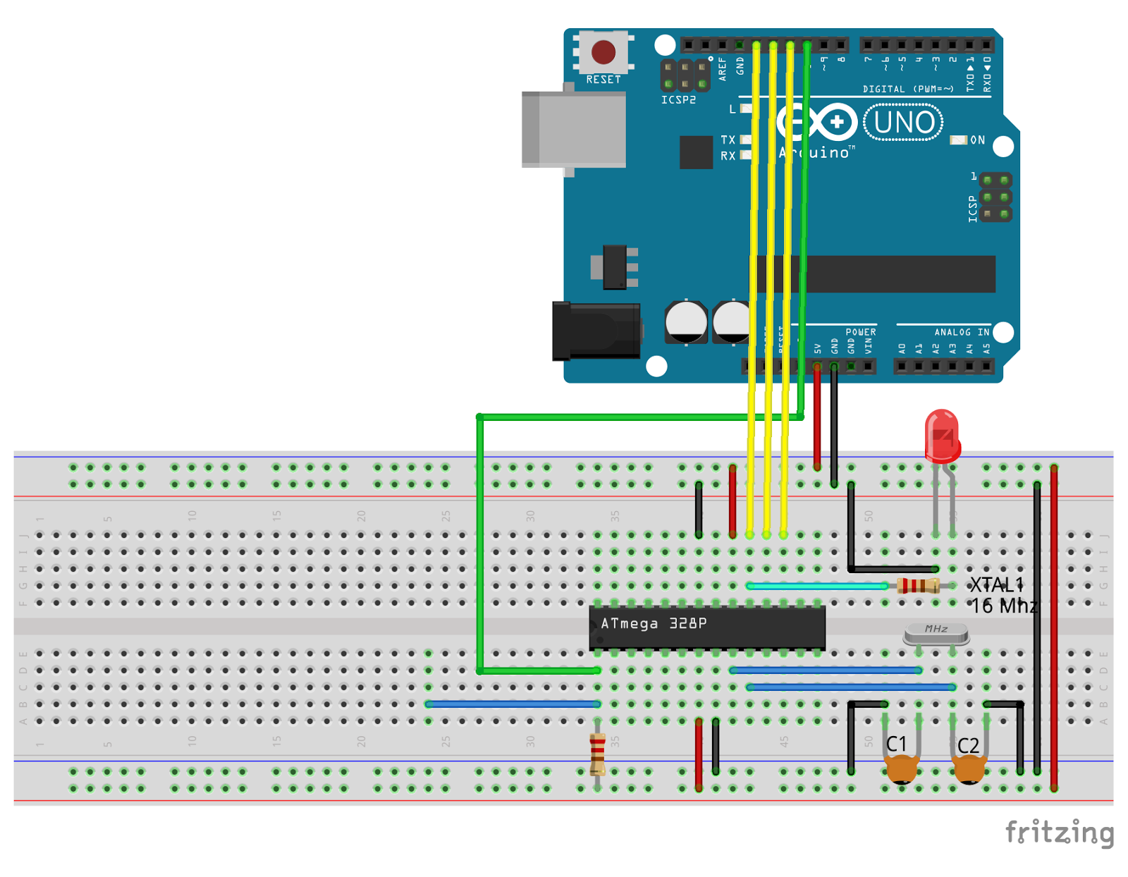 Extra components needed:
- a 16 MHz crystal
- two 22 picofarad capacitors, between the crystal and GND.
- a 10k resistor, between pin 1 of ATMEGA328P and +5V.
- LED and 1K resistor, used in our Blink example. LED cathode connect to GND, anode connect to the 1K resistor, connect to pin 19 of ATMEGA328P.
The basic steps:
- Connect the breadboard to Arduino Uno as shown above.
- Connect Uno to PC using USB.
- Start Arduino IDE, and program the Arduino Uno as ArduinoISP.
- Switch Tools -> Board to our target board.
- Select Tools -> Programmer -> Arduino as ISP.
- Burn Bootloader.
- Compile and upload your sketch.
I suppose the target board is very similar to Nano board, so I select Board of Arduino Nano, and Processor of ATmega328. It success to burn bootloader, but FAIL to upload sketch, with error of:
avrdude: stk500_getsync() attempt x of 10: not in sync: resp=0x1c
As show in this video:
I have to modify boards.txt to add a new board, copy from nano. The file should be locate in the folder arduino-1.5.8/hardware/arduino/avr/. For safety, make a copy before edit.
Find the entry of nano, copy and rename another board, bba.name=BreadBoard Arduino in my case. Modify the content as:
Re-start Arduino IDE after boards.txt modified and saved.
This video show how to edit the file boards.txt:
Finally, we can program the ATmega328 on breadboard using Arduino Uno as ISP, and select our custom BreadBoard Arduino, of processor ATmega328 as target.
Check this video:
Connect your breadboard Arduino to Arduino Uno as shown here:
- a 16 MHz crystal
- two 22 picofarad capacitors, between the crystal and GND.
- a 10k resistor, between pin 1 of ATMEGA328P and +5V.
- LED and 1K resistor, used in our Blink example. LED cathode connect to GND, anode connect to the 1K resistor, connect to pin 19 of ATMEGA328P.
The basic steps:
- Connect the breadboard to Arduino Uno as shown above.
- Connect Uno to PC using USB.
- Start Arduino IDE, and program the Arduino Uno as ArduinoISP.
- Switch Tools -> Board to our target board.
- Select Tools -> Programmer -> Arduino as ISP.
- Burn Bootloader.
- Compile and upload your sketch.
I suppose the target board is very similar to Nano board, so I select Board of Arduino Nano, and Processor of ATmega328. It success to burn bootloader, but FAIL to upload sketch, with error of:
avrdude: stk500_getsync() attempt x of 10: not in sync: resp=0x1c
As show in this video:
I have to modify boards.txt to add a new board, copy from nano. The file should be locate in the folder arduino-1.5.8/hardware/arduino/avr/. For safety, make a copy before edit.
Find the entry of nano, copy and rename another board, bba.name=BreadBoard Arduino in my case. Modify the content as:
##############################################################
# Create custom board of BreadBoard Arduino
bba.name=BreadBoard Arduino

bba.upload.tool=avrdude
#bba.upload.protocol=arduino

bba.bootloader.tool=avrdude
bba.bootloader.unlock_bits=0x3F
bba.bootloader.lock_bits=0x0F

bba.build.f_cpu=16000000L
bba.build.board=AVR_NANO
bba.build.core=arduino
bba.build.variant=eightanaloginputs

## BreadBoard Arduino w/ ATmega328
## -------------------------
bba.menu.cpu.atmega328=ATmega328

bba.menu.cpu.atmega328.upload.maximum_size=30720
bba.menu.cpu.atmega328.upload.maximum_data_size=2048
bba.menu.cpu.atmega328.upload.speed=57600

bba.menu.cpu.atmega328.upload.using=arduino:arduinoisp

bba.menu.cpu.atmega328.bootloader.low_fuses=0xFF
bba.menu.cpu.atmega328.bootloader.high_fuses=0xDA
bba.menu.cpu.atmega328.bootloader.extended_fuses=0x05
bba.menu.cpu.atmega328.bootloader.file=atmega/ATmegaBOOT_168_atmega328.hex

bba.menu.cpu.atmega328.build.mcu=atmega328p

##############################################################
Re-start Arduino IDE after boards.txt modified and saved.
This video show how to edit the file boards.txt:
Finally, we can program the ATmega328 on breadboard using Arduino Uno as ISP, and select our custom BreadBoard Arduino, of processor ATmega328 as target.
Check this video:
Subscribe to:
Posts (Atom)